#RallyCross Start Light
This repository holds the documentation for a starting light circuit developed for use in Pacific Northwest SCCA RallyX events. The purpose of this project is to provide a way to safely signal competitors that they may commence their run when at the starting line.
Benefits over other methods:
- Usable durring the day or for night racing
- Consistant signaling to all competitors
- Ability to remotely control or override
- Operator can stand away from the car to avoid hazards
- Because it looks cool
This repository focuses on the electronics and firmware used to control the start lights. Below are some recomendations for light solutions that can be used with this device.
The device controls as set of red, yellow, and green lights. When first powered up by connecting power the device cycles through all the light colors to allow the user to verify they all work. The default state when the input control is not active is to display a solid red light. When the input control is connected to ground the device begins the start sequence. The start sequence consists of blinking the yellow light three times at one second intervals before going to a solid green. The device will keep the light green for 30 seconds before returning to a solid red. If at any time prior to the sequence completing the operator my deactivate the control input causing the red light to flash repeatedly for a few seconds before returning to a solid red. The operator must deactivate the light prior to being able to activate it for a subsequent start sequence.
- Power consumption: < 30mA (controller only)
- Input voltage range: 5v to 12v DC
- Max light current: 500mA (per channel) DC ONLY
- Input control: switch to ground
- Microcontroller: Arduino Pro Mini (either 3v or 5v)
- Aproximate Size: 65mm x 45mm x 20mm
- Adjustable PWM output: potentiometer
The device will need to be able to control a red, yellow, and green light. It is recomended to use LED bulbs whenever possible to reduce power consumption.
Light Ideas:
- Industrial signal tower with 12v bulbs
- 12v LED panels in a custom housing
TODO: add images
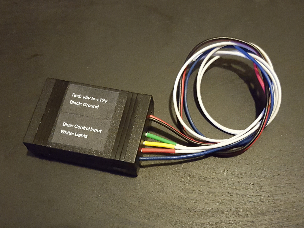
The device has 3 sets of connections: power, light output control, and activation input control.
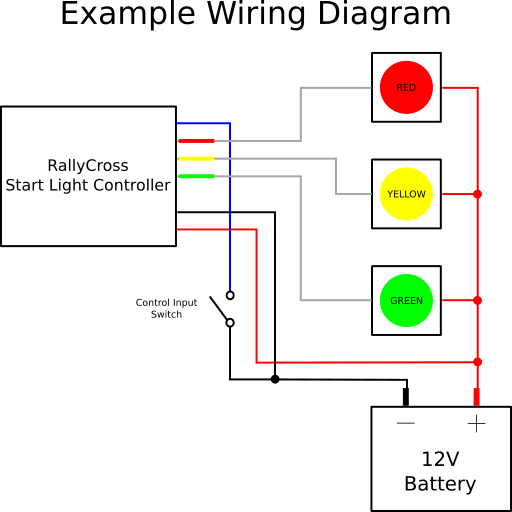
It is recomened to connect the controller to the same power source as your lights, it is required that they at least share a common ground. A 12v SLA battery works well in most all situations. Since one of the lights will be illuminated at any given time you should select a battery that has a capacity to match the length of an event. A simple way to calculate this is to use the equation: battery capacity in amp-hours / light current in amperes = run time in hours.
Warning: make sure to house any electronics or power sources in a weather resistant way to prevent malfunction of the system.
TODO: add images
The lines coming from the control device act as switches to ground. If you need to switch something that needs more power consider using a relay and setting the PWM to its hightest setting.
Warning: The voltage on the light control lines should not exceed the voltage on the power supply lines. If controlling lights at a higher voltage a relay or other switching circuit can be used between the lights and the output lines.
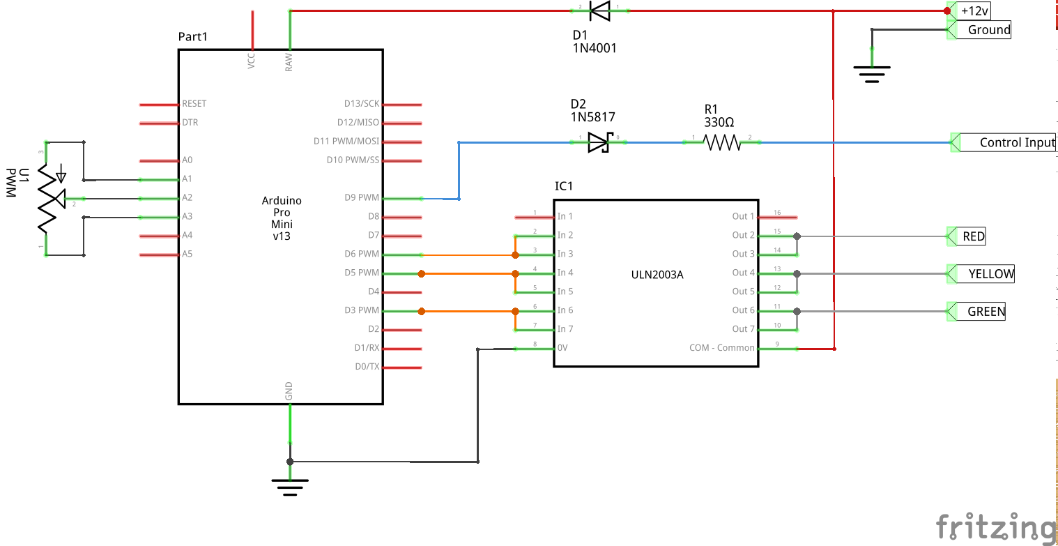
Note: The controller has an internal diode between the light control outputs and the positive power supply. If the loads on the light control lines are not inductive this internal diode connection can be removed by cutting the wire between the positive supply and the common pin on the ULN2003A. This could allow for connecting lights with a higher voltage than the power supply lines directly to the light control lines. Please do not exceed 24v.
Positive supply -> Light -> Light Control Line (red,yellow,green)
TODO: add images
The input control has an internal pull up voltage at the microcontroller. This allows you to use a simple switch to activate the input. Wire the switch between the control input and ground. When the switch is in the on possition it will ground the input activating the start light.
Input Control Line -> Switch -> Ground
TODO: add images
The goal with this circuit is to make it simple enought for the average DIY person with some electronics experience to assemble. I opted to use throughhole components and some strip board to assemble the circuit. The microcontroller used for this project is an Arduino Pro Mini (3v or 5v).
TODO: talk about firmware and how to load it onto Arduino
For the circuit using the strip board layout refrenced above the following enclosure can be used.
- Manufacturer: Pactec
- Model: CNM0000
- Website: www.pactecenclosures.com