Create FG1000 panel variant #1333
Comments
|
The Cessna 172S comes from the factory with the Garmin. It has a few minor changes like fuel injection and a 180hp engine. It might be worth investigating the differences to see just what else would need added. |
|
It's a start!
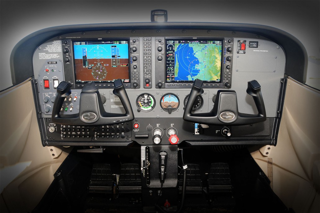
Panel is clean and glass is more or less sized. really not much to this, just move some of the stuff around, add a few small gauges and change the style of some of the switches. |

From the FG engine point of view, i think there is no difference. A 180 hp engine is a 180 hp engine. At my knowledge, an injected engine is much easier to start than a carburetor one. Less capricious. More stable functioning parameters. These are secondary considerations for simulation. By elsewhere, the engine lack of feeding (fuel starvation) at negative g's will make no sense from the carburetor point of view, but it will still exist from the main tanks point of view. Maybe a longer lag?
[/EDIT] Obviously, no primer. (please see my next message for complement) The constant level (collector, float) tank will have no real meaning at all, but this is only a (painful...) cheating, artifact for the two available engines. Unseen from the user, no effect on the performances. |
|
@dany93 wrote
I wrote it too quickly and too short. But a priming procedure is written in the Cessna 172S N552 SP (Engine Model Number: l0-360-L24) POH:
(probably excessively complicated, too much to be accurately rendered in simulation) |
|
@dany93 thanks for the logical thinking. That gives me a sound starting point. I've actually had a chance to work on it a bit. I updated the image above to reflect the changes I have made so far. System wise I temporarily bypassed the primer system if using the glass panel, but I think I will eventually have to create some logic to mimic the fuel pump system. It looks like the electrical bus is a little different than the current c172p as there is a bus 1 and a bus 2. |
|
To be honest, I prefer C172S instead of P variant. |
|
@tonghuix pictures and information would help, educate me if you have the time! I honestly didn't know there were different versions. If using the 172p for the base then I would lean toward whichever version fit that best. One thing I was a bit confused by was the addition of the KAP140. I though the G1000 had an autopilot interface? Also where I put the KAP140 for now is not where it is going to stay if we even use it as it is too far away from the pilot. I have seen it right between the steam gauges and the power and mixture knobs. But i have to rework the panel slightly to do that. |
|
@wlbragg I am training in a C172SP with G1000 variant right now. For the autopilot, it could using either KAP140 or GFC700(which is optional in G1000). If KAP140 is installed, the panel should arrange a place for it; if GFC700 is installed, it would not require dedicate place. C172 G1000 POH: https://6082a08e-f6ee-43ce-a788-78d22ce0c9ae.filesusr.com/ugd/fe4543_d932b973b08d48519e6e0e69b140adb2.pdf C172 Training Supplement: https://s3.amazonaws.com/atp-program-docs/supplements/cessna-172-training-supplement.pdf G1000 Cockpit Ref: https://static.garmincdn.com/pumac/190-00384-12_0A_Web.pdf G1000 Pilot Guide: https://static.garmincdn.com/pumac/190-00498-07_0A_Web.pdf |
|
@tonghuix thank you, the data will really help once I study it. |
@tonghuix what is the difference between the two? The Image above of the work I have already done (the work competed that is above the panel that has the ignition and breakers) looks to be the same as in the reference material you provided. So I am wondering why you made the above comment as if I was modeling it after the p and not the s or sp? So far I was just going off a couple pictures I found searching on the web. |
|
@wlbragg Well, G1000 is an optional instrument, aircraft owner could install it or not, at least theoretically. However, due to 172P is older one, I do not see a "P" model with G1000. Another difference is yoke, SP's yoke looks like a little bigger than P's. SP's visor is more higher, and left and right portion at same level (P's right side a little lower). I just agree @legoboyvdlp 's opinion, it is better we start modeling 172SP which is a newer model. And it is also a good chance to solve #1310 , make our 172 perfect. |
|
Ah, OK, I think I understand, thanks! |
|
That's really nice @wlbragg :) I wish the screen could have some anti-aliasing as its very hard to see and the update rate is somewhat low on the engine parameters of the MFD. I guess these are for the upstream FG1000 not the 172 though. |
|
Here is what it looks like at night, so far. Man, do we have a lot off effects to filter through when making a new variant such as this. I still have a lot of work to do on the panel containing the breakers, Throttle and mixture controls need reposition, others need removed. We need some new style stitches and knobs as well.
|

|
@legoboyvdlp my anti-aliasing is actually shut off for other reasons, this may look better on a FlightGear installation with it turned on. |
|
Cleaned off more of the lower panel.
|

|
Wow this is looking really good! Amazing job 👏 Just a minor thing I seem to notice in this screen shot: the white avionics switch seems to be rotating on a strange axis, look how the left one does not match the one on the right neither at the top nor at the centre of the switches. |
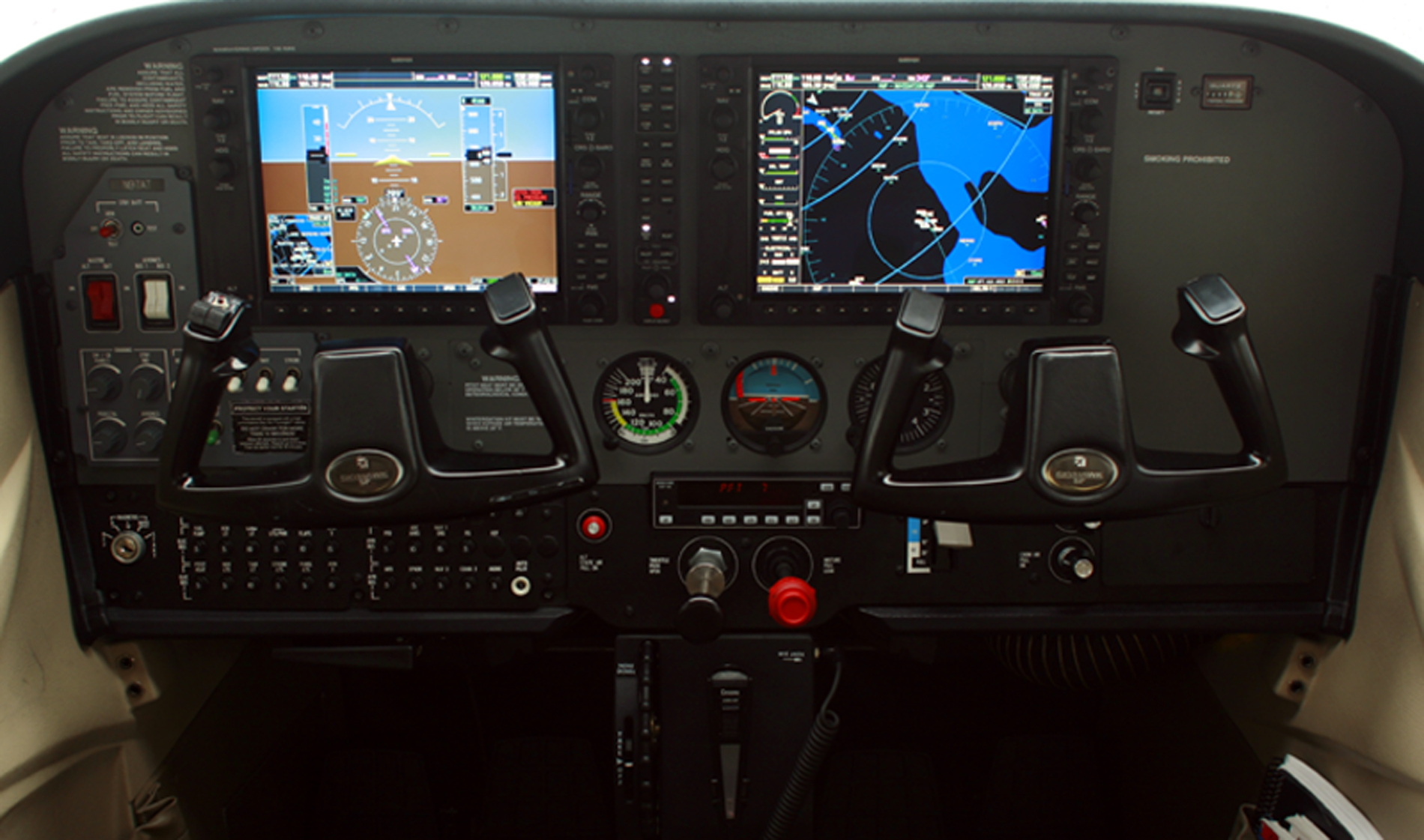
No Audio Panel? It is essential! And you need four nobs to adjust cockpit lights (PFD, MFD, avionics, standby instruments) . Move outside light switches to lefthand under Master and AV switches. 12V port should lower near shut-off valve. |
|
The audio panel is the thin strip between the MFD's? |
Yep! Here is a link https://www.faa.gov/training_testing/training/fits/guidance/media/G1000.pdf, it is better have a look at the graph at Pg2, it explain lots of things. |
|
A little more work done on the panel.
|


|
@tonghuix |
|
I'm thinking of giving the choice of using either the KAP140 or the GFC700 when using the FG1000 variant. |
|
Well, I'm really close to finished with the additional graphics needed for the variant. It's time to add systems and edit systems. The electrical system is probably the biggest issue. Lots of new breakers to tie in. |


|
Here is a graph for electrical system of C172S: https://solarflyer.files.wordpress.com/2020/01/fuel-elec.pdf For the green light, it is only a indicator of STBY BATT, when I turn the switch to TEST position (will spring back to OFF position if no press), it will light up. And any time STBY BATT kicks in, the green light will on as well. For Low Voltage, there should be LOW VOLT annunciation in G1000. For MFD, Avionic switches will control it. |
|
@stuartbuchanan I really like having the option of using the GFC700 built in auto pilot. I do want to keep the ability to choose between the two but that may have to be a variant option instead of a GUI option. I haven't really researched how or if we could do this on the fly. |
Just an info, our school do own some C172Ss equipped with KAP140 autopilot. But most of them are buggy, and not very reliable, mechanics are removing them. A lot of my flight experience with such autopilot are really not good feeling, such us disengage button not work, banking too much, cannot maintain altitude, or twist yoke super sluggishly. |
|
Also, it seems like when I arm the standby battery, the PFD doesn't turn on. |
Hi @wlbragg, For the EIS display, i already have tried to get that working, but i really think there is something missing in the FG1000 core (or i just lack the knowledge to interpret the nasal):
|
|
@hbeni I did look at it and my first reaction was one of intimidation. But I will get back to it and I think it is the way I want to go, I am also intimidated about making my own so I think in the long run adopting yours would definitely be the way to go. It's just a bit more complicated than I was expecting, nothing about what you did, only my own comfort in my abilities to adopt and implement it. |
|
@D-ECHO @NewoIsTaken |
|
Wow, don't know how that happened, accidentally closed the issue there for a time? |
Ugh, the KAP140 exists in early G1000 C172P's only because the GFC700 was not yet certified at the time. The integration is horrible, the Garmin only drives it left-right and you need to set altitude, baro, vertical speed etc modes in the KAP140. There is actually a single turn&bank gauge behind the right screen (MFD) of the G1000 that is the attitude / heading reference for the KAP140, the G1000 just says "turn left, now turn right, now straight". Ugh, The G1000 has all that functionality but it cannot be used (and like the alt selector "works" in the G1000 but it does absolutely nothing apart from being a "postit note" so you can remember the number if you dial it in.) - that was the only option they had when they wanted to get the G1000 in the plane if they wanted an autopilot. I mean, by all means, give a choice but I don't understand who would be such a masochist to choose it if GFC700 is an alternative... :-) |
|
I'll take a look at the CHT and battery amps. The problem is almost
certainly that the wrong properties are being referenced in the EFIS.nas
RE: KAP140 - I suspect you'd struggle to get accurate integration between
the KAP140 and the FG1000. You'd probably need to add an Emesary node to
listen to the correct messages from the UI and then pass them onto the
KAP140. I really don't think it's worth the effort.
…-Stuart
On Thu, Dec 17, 2020 at 6:34 PM Tuomas Kuosmanen ***@***.***> wrote:
I'm thinking of giving the choice of using either the KAP140 or the GFC700
when using the FG1000 variant.
I need to see if I can easily hook up the GFC700 and if it is tuned .at
all for the c172
Ugh, the KAP140 exists in early G1000 C172P's only because the GFC700 was
not yet certified at the time. The integration is horrible, the Garmin only
drives it left-right and you need to set altitude, baro, vertical speed etc
modes in the KAP140. There is actually a single turn&bank gauge *behind
the right screen (MFD) of the G1000* that is the attitude / heading
reference for the KAP140, the G1000 just says "turn left, now turn right,
now straight". Ugh,
The G1000 has all that functionality but it cannot be used (and like the
alt selector "works" in the G1000 but it does absolutely nothing apart from
being a "postit note" so you can remember the number if you dial it in.
I mean, by all means, give a choice but I don't understand who would be
such a masochist to choose it if GFC700 is an alternative... :-)
—
You are receiving this because you were mentioned.
Reply to this email directly, view it on GitHub
<#1333 (comment)>,
or unsubscribe
<https://github.com/notifications/unsubscribe-auth/AC7C5GBKCBG6QUVXV7WQ7DLSVJFKHANCNFSM4QHO3THQ>
.
|
That is why I choose to leave the choice. Because of statements like "our school do own some C172Ss equipped with KAP140 autopilot". I think of it the same I do about any upgrades done to any aircraft. We are always improving on systems and technology in the real world, but that doesn't erase the history of what used to be, I really think it is important to retain that history when possible and practical. If I hadn't evolved this variant in the steps I took, which was using the KAP140 first, then adopting the GFC700, just like the timeline in real life, I may not have given this choice. But once the work is done, I see no need to remove it. It is a reality that actually existed and I guess I leave it mostly for nostalgia. |
@stuartbuchanan |
@stuartbuchanan |
|
What i don't really understand - why does the G1000 do its own calculations on fuel, if it could just use the output of the tanks sensors? |
|
@wlbragg - Yes, you're right. I was getting confused between the EGT and
CHT gauges.
On Thu, Dec 17, 2020 at 9:08 PM Benedikt Hallinger wrote:
What i don't really understand - why does the G1000 do its own
calculations on fuel, if it could just use the output of the tanks sensors?
I think it's because IRL the fuel flow sensors are far more accurate than
the fuel tank sensors.
BTW - I've fixed the issue that meant you have to put files into fgdata.
I'll email you a patch.
|
|
@NewoIsTaken @D-ECHO |
|
@wlbragg No problem, just tell us if you uncover something! |
|
Unfortunately, this still happens with newest FG and c172 |
|
@D-ECHO @NewoIsTaken I just pushed a small change to the interface controller code via a patch from Stuart. Please pull a fresh copy, make sure you clear your aircraft data, and see if your current issue is fixed. If not, make sure you send me the exact error. Because I am getting no errors and the backup bat logic is working correctly for me. |
|
@wlbragg, PFD comes on right as I hit the standby battery on switch now! |
|
@NewoIsTaken Thanks! |
|
I pushed some new interior lighting logic for the panel knobs. All that is left for the interior lighting is the Pedestal light which will be a new lightmap. I'm, not sure how much the electrical has changed from my last push, only that I am pretty happy with it at this point. |
Great! Thanks! |
|
Notes: Why are all instruments now inheriting c172p-interior-radiance -> c172p-interior |
|
@wlbragg I will try to test out the FG1000 today or sometime soon. |
|
Notes to myself: |
|
OK, I pushed a major refactoring of the c172sp electrical. I think it is in really good shape. It includes stby amp and volt readings for the EIC display once I get the changes pushed to fgdata. Using the formula amps * bus volts for each power supply circuit and then converting the total watts back to amps using watts / bus volts corrects the electrical power usage in electrical.nas and electrical-fg1000.nas. So it is easy to assign the actual draw per instrument. If anyone has the time to really look at the numbers there are some debug properties that can be un-commented out in order to watch what's going on in real time. |
|
Another major refactoring pushed. Also cleaned up flight recorder, MP, hot spot text. The major refactoring was to isolate c172p exclusive content from c172sp exclusive content. It should lighten the load slightly for all variants and helps group things in a more understandable fashion. |
I hope there isn't already an issue for this. I couldn't figure out how to effectively search through the existing issues.
Because glass is now the future of aircraft, I think we need a glass variant. I did the PA-18 and it really wasn't that difficult to retrofit it. We could do the same thing with our flagship and probably should. I think it would have to be done the same way as I did the PA-18 and it would have to have it's own set file and that would be the only way to access it. Not on the fly like the gear and engine changes. It's too heavy and cause the other PA-18 variants to lag even when in the background.
What I think is needed most for this is just some good cockpit reference material the matches our c172p model as best we can find. This winter when I'm holed up maybe I can start on this with a little help here and there.
The text was updated successfully, but these errors were encountered: